
Frequency Range & Functionality
-
Operating Frequency: 403 MHz to 520 MHz — this places it in the UHF (Ultra High Frequency) range, commonly used for services such as two-way radio systems, telemetry links, data radios, PMR (Professional Mobile Radio), and some industrial communication applications.
-
The antenna is optimized to operate efficiently across this wide UHF band, maintaining consistent performance throughout.
-
It supports linearly polarized signals (vertical or horizontal), depending on how it’s mounted.📈 Gain & Directionality
-
Gain: 9 dBi — this means the Yagi antenna amplifies the effective radiated signal in its main direction by 9 decibels over an isotropic (perfectly uniform) radiator.
-
A 9 dBi gain is a moderate directional gain, offering a good balance between forward focus and beamwidth. It allows improved communication range and stronger received signals in the targeted direction compared to omnidirectional antennas.
-
Higher gain antennas narrow the radiation pattern, concentrating energy in one direction and reducing reception from unwanted angles.🧱 Antenna Construction
-
Constructed from high-quality aluminum elements (boom and directors) for low weight, corrosion resistance, and outdoor durability.
-
Elements and boom are usually welded or rigidly fastened to ensure mechanical stability and consistent RF performance.
-
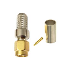
Often supplied with an N-type female connector for reliable connection to standard 50 Ω coaxial cables commonly used in RF installations.
-
Mounting hardware allows installation on masts, poles, or brackets with orientation adjustment (vertical/horizontal polarization). scan-antenna.com
🛰️ Performance Characteristics
-
VSWR (Voltage Standing Wave Ratio): Typically designed to achieve a low VSWR (e.g., <1.5:1), ensuring efficient power transfer with minimal reflected energy.
-
Front-to-Back Ratio: Directional Yagi antennas like this often feature a strong front-to-back ratio (commonly >15–20 dB), meaning signals from the rear are much weaker than signals in the forward direction — reducing interference from behind.
-
Beamwidth: The horizontal and vertical beamwidths determine how tightly the antenna ‘focuses’ energy and are balanced to offer focused coverage while still tolerating small aiming inaccuracies.
-
Impedance: Standard 50 Ω design that matches most RF equipment and coaxial feed lines.
🌦️ Environmental & Mechanical
-
Built to withstand outdoor environments — including temperature changes, rain, and wind loads — making it suitable for rooftop or mast installations.
-
Light mechanical weight simplifies installation on towers, poles, or mobile platforms.
-
Depending on specific product specs, wind survival and durability ratings vary but are typically engineered for robust use.
📡 Typical Uses & Applications
A 403–520 MHz Yagi antenna with 9 dBi gain is ideal for:
• Point-to-point or point-to-multipoint UHF RF links.
• Wireless data communication systems in industrial, commercial, or rural environments.
• Two-way radio systems, telemetry, SCADA, and dispatch communications.
• Base station antennas where concentrated coverage toward another station improves signal strength.
• Amateur radio setups requiring directional gain within this band.
Reviews
There are no reviews yet.