
Design Concept:
Yagi-Uda Antenna: This antenna design consists of a series of elements arranged along a boom. The key components are:
Driven Element: This element is connected to the feedline and where the RF signal is applied or received.
Reflector: Positioned behind the driven element, it reflects the signal towards the driven element, enhancing gain.
Directors: Located in front of the driven element, these elements focus the signal in a specific direction, improving gain and directivity.
Key Features:
High Gain:
14 dBi Gain: Provides substantial signal amplification in the direction the antenna is pointed. This high gain helps in extending the effective range and improving signal clarity compared to antennas with lower gain.
Frequency Range:
800-2500 MHz: Spans from UHF to some higher frequencies, covering cellular bands (such as GSM, LTE, and 5G) and some satellite communication frequencies.
Directional Pattern:
Focused Beam: Provides a directional radiation pattern, which helps in improving signal reception and transmission in a specific direction while reducing interference from other directions.
High Front-to-Back Ratio: Offers a high front-to-back ratio, which helps minimize signals from the rear.
Construction:
Materials: Typically constructed from high-quality, durable materials like aluminum or stainless steel, ensuring long-term reliability and resistance to environmental factors.
Design Specifications:
Frequency Range: 800-2500 MHz
Element Lengths: Elements are sized according to the operating frequencies. Longer elements are used for lower frequencies (800 MHz), and shorter elements for higher frequencies (2500 MHz).
Element Spacing: Spacing between elements is optimized to achieve the desired gain and directivity across the frequency range.
Element Configuration:
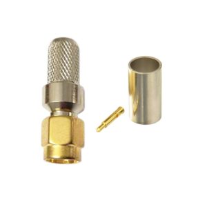
Driven Element: Designed to match the impedance of the feedline, usually 50 ohms.
Reflector and Directors: The arrangement and number of reflectors and directors are optimized to achieve the 14 dBi gain. More directors typically result in higher gain and better directivity.
Materials:
Elements: Often made from lightweight, corrosion-resistant materials such as aluminum or stainless steel.
Boom: The boom is generally constructed from strong, lightweight materials to support the elements and ensure stability.
Feed Point:
Impedance Matching: Designed to match a 50-ohm impedance for efficient power transfer and minimal SWR (Standing Wave Ratio).
Construction and Installation:
Assembly:
Elements and Boom: Assemble the elements onto the boom according to the design specifications. Ensure precise alignment and secure attachment to achieve optimal performance.
Feed Line: Connect the feed line to the driven element using high-quality coaxial cable to minimize signal loss.
Mounting:
Pole or Mast Mount: Securely mount the antenna on a pole or mast. Ensure that the antenna is properly aligned and stable to maintain performance.
Height and Location: Mount the antenna as high as possible and away from obstructions to enhance signal reception and transmission.
Tuning and Testing:
SWR Measurement: Measure the SWR across the frequency range to ensure it is within acceptable limits. Adjust the antenna or matching network as needed.
Performance Testing: Verify the antenna’s performance to ensure it is effectively amplifying and directing signals across the intended frequency range.
Applications:
Cellular Communication: Suitable for improving signal strength in cellular networks, including GSM, LTE, and 5G systems.
Broadcasting: Effective for receiving and transmitting TV and radio signals where high gain and directionality are required.
Amateur Radio: Ideal for amateur radio operators needing a high-gain antenna for long-distance communication across a broad frequency range.
Satellite Communication: Can be used for satellite communication within the frequency range, depending on the specific design.
Maintenance:
Regular Inspection: Periodically check the antenna for wear, damage, or corrosion, particularly if installed outdoors.
Cleaning: Clean the elements and feed point to maintain optimal performance and extend the lifespan of the antenna.
Reviews
There are no reviews yet.