
Key Features:
1. High Gain:
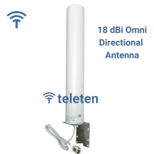
– 18 dBi Gain: Provides a significant increase in signal strength compared to lower-gain antennas. This high gain helps in extending the range and improving signal clarity.
2. Wide Frequency Range:
– 800-2500 MHz: Covers a broad range of frequencies, including GSM, LTE, and some satellite communications, making it versatile for various applications.
3. Directional Pattern:
– Directional Radiation: The Yagi antenna focuses energy in one direction, which helps in minimizing interference and improving signal strength from the desired direction.
4. Construction Material:
– 10 Meter Wire Elements: The antenna’s elements are typically constructed from durable wire or tubing. For a Yagi antenna with 10-meter elements, these are usually designed to handle the required frequencies effectively.
Design Specifications:
1. Frequency Range: 800-2500 MHz
– Element Lengths: Elements need to be cut to specific lengths for different frequencies within the range. For high frequencies, the elements are shorter, and for lower frequencies, they are longer.
– Element Spacing: The spacing between the elements also varies according to frequency and design specifics. Proper spacing is critical to achieve the desired performance.
2. Element Configuration:
– Driven Element: The length and position of the driven element are critical for optimal performance.
– Reflector and Directors: The number and spacing of reflectors and directors are designed to maximize gain and directivity.
3. Construction Materials:
– Elements: Typically made from aluminum or other lightweight, corrosion-resistant materials.
– Boom: The boom that supports the elements is usually made from a sturdy material like aluminum or fiberglass.
4. Feed Point:
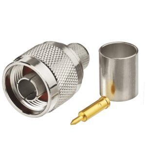
– Impedance Matching: The feed point is designed to match the antenna to the transmission line, usually 50 ohms, to ensure efficient power transfer.
Construction and Installation:
1. Assembly:
– Elements and Boom: Assemble the elements onto the boom according to the design specifications. Ensure that the elements are properly aligned and secured.
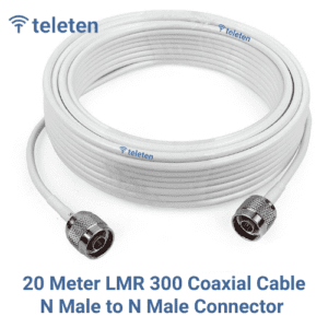
– Feed Line: Connect the feed line to the driven element. Use high-quality coaxial cable to minimize signal loss.
2. Mounting:
– Pole or Mast Mount: Secure the antenna to a mast or pole. Ensure that it is mounted securely and is aligned properly for accurate directionality.
– Height: Mount the antenna as high as possible and in a location free from obstructions to maximize performance.
3. Tuning and Testing:
– SWR Measurement: Measure the Standing Wave Ratio (SWR) across the frequency range to ensure it is within acceptable limits. Adjust the antenna or matching network if necessary.
– Performance Testing: Test the antenna’s performance to verify that it is receiving and transmitting signals effectively across the desired frequency range.
Applications:
1. Communication Systems: Ideal for high-frequency communication systems, including GSM, LTE, and satellite communications.
2. Broadcasting: Useful for receiving or transmitting broadcast signals where high gain and directionality are required.
3. Amateur Radio: Suitable for amateur radio operators needing high gain in specific directions for long-distance communication.
Maintenance:
– Regular Inspection: Periodically check the antenna for signs of wear, corrosion, or damage, especially if installed outdoors.
– Cleaning: Clean the antenna elements and feed point as needed to maintain performance and longevity.
Reviews
There are no reviews yet.