
Frequency Range: 700 MHz to 3500 MHz
The coupler is designed to operate effectively within this frequency range, ensuring minimal signal distortion and accurate performance.
Coupling Factor: 15 dB
This indicates that the output signal strength is reduced by 15 dB compared to the input signal strength. A coupling factor of 15 dB means that the coupled signal is approximately 1/31.6 of the input signal power.
Directivity: Typically 15 dB to 20 dB
Directivity measures how well the coupler isolates the input signal from the coupled output. Higher directivity values indicate better isolation between the input and coupled outputs.
Insertion Loss: Typically 0.3 dB to 0.7 dB
Insertion loss represents the amount of signal power lost due to the insertion of the coupler into the transmission line. Lower values are preferable, indicating minimal signal attenuation.
Return Loss: Typically 15 dB to 20 dB
Return loss measures how well the coupler matches with the transmission line. Higher return loss values indicate better impedance matching and less reflected signal.
Power Handling: Typically 10 W to 50 W
The maximum power the coupler can handle without damage. This depends on the design and construction materials of the coupler.
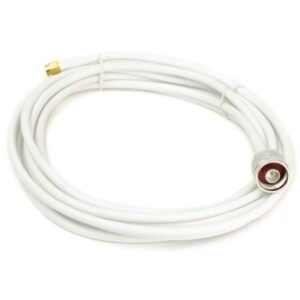
Connector Type: N-type Female
The coupler is equipped with N-type female connectors, which are durable and suitable for high-frequency applications. These connectors are threaded for secure connections.
Construction: Typically made from aluminum or brass with a high-quality dielectric material
The construction materials impact the coupler’s performance, durability, and frequency response.
Dimensions: Varies depending on the specific model
Size and form factor will vary; ensure that the coupler fits within your system’s physical constraints.
Environmental Conditions:
Temperature Range: Typically -40°C to +85°C
Humidity: Typically up to 95% non-condensing
Reviews
There are no reviews yet.