This type of assembly is used in various applications, including telecommunications, networking equipment, and RF systems where high-frequency signal transmission and accurate connections are essential. The SMA female RP connector’s design and solder mounting method ensure a dependable and high-performance solution for demanding environments.
SMA F RP PCB SOLDER
- Preparation:
– Inspect the PCB: Ensure the PCB is clean and the solder pads or holes for the SMA connector are correctly prepared. The pads should be free of contaminants and aligned with the connector’s pins.
– Prepare the Connector: Check that the SMA female RP connector is clean and ready for assembly. It will have pins or leads designed for soldering onto the PCB. - Insert the Connector:
– Position the Connector: Insert the SMA female RP connector into the designated holes or align it with the pads on the PCB. The pins of the connector should fit into the PCB’s holes or align with the solder pads.
Soldering Steps:
– Secure the Connector: Use a fixture or tape to hold the connector in place while soldering if necessary. Ensure that the connector is properly aligned and does not shift.
– Solder the Pins:
– Heat each pin of the SMA connector with a soldering iron.
– Apply solder to each pin and its corresponding PCB pad or hole. Ensure that the solder flows around the pin and pad, forming a strong and reliable connection.
– Avoid using excessive solder, which can cause solder bridges or other issues. Aim for a clean, controlled application.
– Check Alignment: Continuously verify that the connector remains properly aligned with the PCB during soldering to prevent misalignment.
- Final Steps:
– Inspect the Solder Joints: After soldering, examine each solder joint to ensure it is properly bonded. Look for clean, shiny solder joints without cold solder or bridges. Verify that each pin is securely attached to its pad.
– Clean the Area: If necessary, clean the soldered area with isopropyl alcohol or another suitable cleaning agent to remove any flux residue.
– Test the Connection: If possible, use testing equipment to confirm that the soldered SMA connector performs correctly and meets the required specifications for signal integrity and performance.
Applications:
– SMA Female RP Connectors with PCB Soldering are used in RF and microwave applications where a stable and reliable connection is crucial. The reverse polarity design helps to prevent accidental mismatching, which can be important in certain RF systems.
– Soldering ensures a permanent and robust attachment to the PCB, providing a reliable mechanical and electrical connection for fixed installations.
₹99 ₹65
⚡ 🚚 Lightning Fast Delivery in 4-7 Business Days – Pan India
💸 Cash On Delivery Available
💰 Lowest Prices
The prices on our website are the lowest. Don’t trust us, compare it with Amazon or Flipkart immediately. If you ever find our prices higher than any website, let us match it for you.
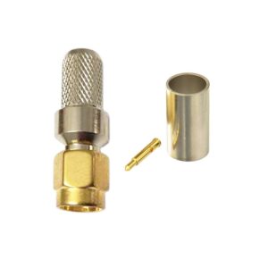
This SMA female reverse polarity (RP) connector is intended for soldering onto a PCB. It provides a secure and stable connection for high-frequency signals, suitable for RF applications requiring reverse polarity configuration.
The term ”SMA F RP PCB SOLDER” refers to a specific type of SMA female connector designed for soldering onto a printed circuit board (PCB). Here’s a breakdown of each component:
Components:
1. SMA Connector (Female):
– SMA (SubMiniature version A): A coaxial RF connector used for high-frequency applications, typically up to 18 GHz. SMA connectors are known for their compact size and reliable performance.
– Female (F): The female SMA connector has a receptacle that accepts the central pin of a male SMA connector. This type of connector generally has a threaded coupling mechanism for a secure connection.
2. RP (Reverse Polarity):
– RP (Reverse Polarity): This indicates that the connector has a reverse polarity configuration, which is a variation of the standard SMA connector. In RP SMA connectors, the center pin and socket are reversed compared to standard SMA connectors. This means that the male connector will have a recessed pin, and the female connector will have a protruding socket. This design helps prevent mismatching with standard SMA connectors and is used to avoid accidental cross-connects in RF systems.
3. PCB Solder:
– PCB (Printed Circuit Board): A board used to mechanically support and electrically connect electronic components. The PCB has copper pads or holes where components are mounted and soldered.
– Solder: This indicates that the SMA female connector is designed to be soldered onto the PCB. The connector will have pins or leads that are inserted into holes or aligned with pads on the PCB and then soldered to create a stable, reliable connection.
Weight | 0.1 kg |
---|
Free Shipping
On orders above 999/-
14 Days Return
No Questions Asked
Secure Payment
Secure Server
100% GST Bill
All Original Products

Proudly Made in India
Teleten has always been a staunch supporter and advocator of Make In India. We live in the most diversified country with unmatched talent and creativity. We are the biggest democracy in the world with second largest population. As an organization, we firmly believe that the whole society needs to grow to facilitate a holistic development of any company/organisation.
Considering the ongoing pandemic, we realise that the need of the hour is to boost our organization in our own backyard. We aim to raise employment opportunities from an already existent Indian talent base, towards a better and a sustainable future. In order to achieve this we must:
Buy Any Indian Product.
But Buy Only Indian Products.
Be Vocal for Local.
We are proud to be the part of this great initiative by Indian Government. We hope more people understand the importance of this initiative and more consumers become rational to buy only Indian products.
We Understand You Can Still Have Questions
Do you have a doubt or a concern? Not sure what to get yet? Dont know what will work best for you? No problem. Our technical team can answer all your questions.