- Prepare the Cable:
– Strip the Outer Jacket: Use a cable stripping tool to remove about 1.5 to 2 inches of the outer jacket from the LMR 400 cable. Be careful not to damage the braided shield underneath.
– Expose the Shielding: Pull back the braided shield to reveal the dielectric insulation. Trim any excess shielding to ensure it fits neatly inside the connector.
– Strip the Dielectric: Strip the dielectric insulation to expose the center conductor. The length of exposed center conductor should be about 1/4 to 1/2 inch, depending on the connector’s specifications.
Prepare the Connector:
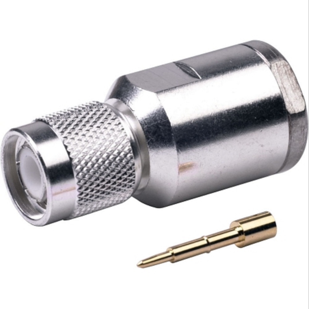
– Slide on the Clamp or Ferrule: If the TNC male connector includes a separate clamp or ferrule, slide it onto the cable before inserting the cable into the connector. This clamp will be used to secure the cable and the shield.
– Insert the Cable: Insert the prepared end of the LMR 400 cable into the TNC male connector. Ensure that the center conductor aligns with the center pin of the connector and the shield aligns with the clamp area.
- Secure the Connection:
– Clamp the Connector: Use a wrench or pliers to tighten the clamp or ferrule around the cable. This action secures the connector to the cable, ensuring a solid mechanical connection. Tighten evenly to avoid gaps or uneven pressure.
– Crimp the Center Pin: If the connector uses a crimp-style center pin, use a crimping tool to crimp the center pin onto the center conductor of the cable. Ensure the center conductor is fully inserted into the pin before crimping. - Assemble and Insulate (Optional):
– Apply Heat Shrink Tubing: For additional insulation and strain relief, slide heat shrink tubing over the joint and apply heat to shrink it tightly around the connector and cable.
– Inspect the Assembly: Check that the connector is securely attached, the clamp and center pin are properly crimped, and there are no loose parts. Ensure the center conductor and shield are properly connected. - Test the Connection:
– Verify Connections: Ensure the connector is firmly attached and there are no loose parts.
– Test Signal: Use appropriate testing equipment to confirm that the connection is functioning correctly and that there are no signal issues.

Reviews
There are no reviews yet.