View cart “LMR 300 Low Loss RF Coaxial Cable – N Male to SMA Male Connector – For Router – 25 Meter” has been added to your cart.
Sale!
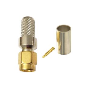
SMA M RA PCB SOLDER
₹125₹90
Preparation:
– Inspect the PCB: Ensure the PCB is clean and free of any debris or contaminants. Verify that the solder pads or holes where the SMA connector will be mounted are properly prepared and aligned.
– Insert the Connector: Position the SMA right-angle connector in the designated holes or pads on the PCB. The connector’s pins or leads should fit through the PCB holes or align with the pads
Soldering Steps:
– Secure the Connector: If necessary, use a fixture or tape to hold the connector in place while soldering.
– Solder the Pins:
– Heat each pin of the SMA connector with a soldering iron.
– Apply solder to the pin and the corresponding PCB pad or hole. Ensure that the solder flows around the pin and pad, creating a strong electrical connection.
– Avoid applying too much solder, which can cause solder bridges or other issues.
– Check Alignment: As you solder each pin, ensure that the connector remains properly aligned with the PCB and does not shift out of place.
Final Steps:
– Inspect the Solder Joints: After soldering, inspect each connection for proper bonding. Look for clean, shiny solder joints without cold solder or solder bridges. Ensure that each pin is securely attached to its pad.
– Clean the Area: If necessary, clean the soldered area with isopropyl alcohol or another suitable cleaning agent to remove any flux residue.
– Test the Connection: If possible, use RF testing equipment to verify that the soldered SMA connector performs correctly and meets the required specifications.
Applications:
– SMA Right-Angle PCB-Mount Connectors are used in RF and microwave applications where space is limited, and a direct connection to a PCB is required. The right-angle design helps with routing cables in confined spaces or specific orientations.
– Soldering is preferred for mounting connectors on PCBs because it provides a permanent and reliable connection. This is crucial for ensuring long-term performance and stability in electronic devices.
This SMA male right-angle connector is intended for soldering onto a PCB. It provides a secure and stable connection for high-frequency signals, ideal for RF applications requiring a right-angle configuration.
Weight
0.1 kg
Reviews
There are no reviews yet.
Be the first to review “SMA M RA PCB SOLDER” Cancel reply
")


Reviews
There are no reviews yet.