View cart “SMA Connector N Male for LMR 400 RF Coaxial Cable (Pack of 4)” has been added to your cart.
Sale!
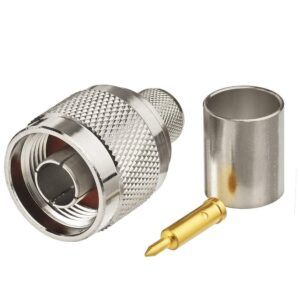
UHF Male LMR 400 Solder
₹149₹99
Prepare the Cable:
– Strip the Outer Jacket: Use a cable stripping tool to remove approximately 1.5 to 2 inches of the outer jacket from the LMR 400 cable. Be careful not to damage the underlying braided shield.
– Expose the Shielding: Pull back the braided shield to reveal the dielectric insulation. Trim any excess shielding to make sure it fits neatly inside the connector.
– Strip the Dielectric: Strip the dielectric insulation to expose the center conductor. The length of exposed center conductor should be about 1/4 to 1/2 inch.
Prepare the Connector:
– Insert the Cable: Insert the stripped end of the LMR 400 cable into the UHF male connector. Ensure the center conductor aligns with the center pin of the connector, and the shield aligns with the connector’s outer sleeve or ferrule.
Solder the Center Pin:
– Heat the Pin: Place the soldering iron tip against the center pin of the UHF connector and allow it to heat up.
– Apply Solder: Feed solder into the joint where the center conductor meets the center pin. Make sure the solder flows evenly around the conductor and pin for a strong, reliable connection.
– Let It Cool: Allow the solder joint to cool and solidify naturally. Avoid moving the connector while the solder is cooling to prevent a cold solder joint.
Solder the Shield:
– Heat the Ferrule: If the UHF male connector has a ferrule or outer sleeve for the shield, heat this area with the soldering iron.
– Apply Solder: Feed solder into the joint between the shield and the ferrule. Ensure the solder flows evenly to create a good connection between the shield and the connector’s ferrule.
– Let It Cool: Allow the solder to cool and solidify naturally.
Assemble and Insulate (Optional):
– Apply Heat Shrink Tubing: Slide heat shrink tubing over the joint and apply heat to shrink it tightly around the connector and cable. This provides additional insulation and strain relief.
– Inspect the Assembly: Verify that all solder joints are clean and well-formed. Ensure the connector is securely attached to the cable and there are no loose parts.
Test the Connection:
– Verify Connections: Check the assembled connector for proper connection and stability.
– Test Signal: Optionally, use appropriate testing equipment to ensure the connection is functioning correctly and that there are no signal issues
The UHF Male LMR 400 Solder connector is designed for use with LMR 400 cables, providing a reliable and durable connection. The solder termination ensures excellent electrical contact and minimal signal loss, suitable for high-power RF applications. This connector is commonly used in broadcasting, telecommunications, and other RF systems where superior performance is required. Its robust construction and precise engineering provide long-lasting reliability, making it ideal for professional installations in challanging enviorments. |
Weight
0.1 kg
Reviews
There are no reviews yet.
Be the first to review “UHF Male LMR 400 Solder” Cancel reply


Reviews
There are no reviews yet.